Introduction
This trap antenna is designed to cover the 10m-15m-20m-40m bands and resonate on the PSK31/FT8 frequencies [1] and Table 1 with operation on SSB QRP frequencies desirable.
The building of the antenna was inspired by [2] and [3].
Summary
The write up here represents the third iteration of the design. In the first iteration the traps were wound for resonance a few 100’s of kHz below the edge of the higher band and weren’t particularly well matched for resonant frequency. The antenna resonated low on all bands and the elements required significant trimming to get resonance anywhere near the FT8 segments of the bands. This, combined with the fact that the VSWR was still unacceptably high on 15 m meant that another iteration was required.
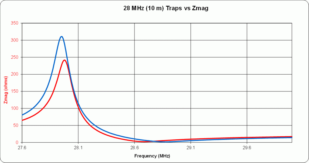
For the second iteration I adjusted the traps to resonate within a few kHz of the lower edge of the higher band and made sure that each trap pair was resonant to within a few kHz. The measurements for the adjusted traps are shown below in Figures 1 to 3. The antenna was re-constructed and due to the excessive pruning from the first attempt the antenna was now measured to be resonant at too high a frequency on all bands with unacceptably high VSWR on the FT8 frequencies.
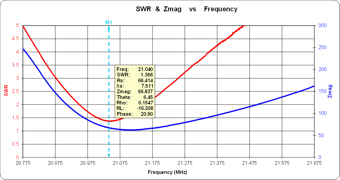
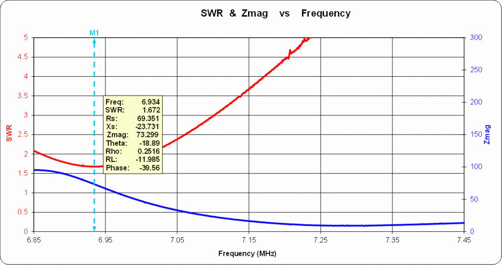
It was calculated that simply replacing the 10 m elements with the original calculated length would bring all bands to resonance at the lower end of each band. Plots of VSWR and |Z| having replaced the 10 m elements are shown below in Figures 5 to 8.
Trap Construction
The traps were built using T106-6 Iron Powder torrid cores [4] wound with the appropriate number of turns of 14 SWG wire [5]. Calculation of the number of turns required was from a spreadsheet created by myself [6] to analyse “what-if” for different cores and inductor/capacitor ratios. Resonance was achieved by using 100 pF Silver Mica capacitors [7] in series/parallel combination to give between 50 pF and 200 pF as required to achieve resonance on the desired band.
Resonance just below the bottom of each band was chosen for the reasons outlined in [3]. Furthermore operation off the resonant frequency reduces the circulating voltages in the resonant circuit and hence the voltage requirement on the capacitors.
Trap Measurement
Traps were measured on the SARK110 using |Z| and <Zs as described on the SARK110 website. SARK Plots was used to control the SARK110 with the results of the measurements being saved to Excel for importing into Zplots [9] for additional analysis. The figures below show the resonance for each trap pair:


Variation in |Z| between trap pairs is likely down to slight variations in the winding and construction of the traps but they are resonant within less than 30 kHz difference between each pair.
Having tuned the traps using my SARK-110 vector impedance analyser the cores were then mounted on bases cut from FR4 PCB drilled appropriately as per the template diagram below [8] to accept the core and antenna elements.

Antenna Construction
The antenna centre is an LDG RBA 1:1 balun mounted on “T” piece mounded from Polymorph plastic appropriately drilled to mount the balun and thread the antenna wire though. Antenna elements are constructed from coated Flexweave style wire from Nevada Radio (UK). The initial element lengths were calculated for a standard wire dipole in the knowledge that there would be some significant trimming to do to compensate for the loading effects of the traps.
| FT8 | PSK31 | SSB QRP | Length per leg (m) | Delta (m) |
| 7.0740 | 7.035 | 7.090 | 10.08 | 5.01 |
| 14.074 | 14.070.150 | 14.285 | 5.07 | 1.68 |
| 21.074 | 21.080.150 | 21.285 | 3.38 | 0.84 |
| 28.074 | 28.120.150 | 28.360 | 2.54 | 0 |
Table 1: FT8/PSK31/SSB QRP Frequencies (MHz) and Calculated Antenna Element Lengths
Antenna Tuning
The plots were saved on the SARK-110 and downloaded to a computer for further analysis in Zplots by AC6LA [9]. The antenna is tuned starting with the 10m elements checking for lowest VSWR on the SARK-110 for the frequency of interest and progressing to each lower frequency. Plots below for each frequency:


Analysis
10 m, 15 m and 40 m are slightly low in resonance and 20 m is above FT8 frequency. Trimming 10 m will likely bring 15 m to resonance on FT8 frequency and move 20 m slightly higher, 40 m may require additional trimming.
| F1 (MHz) | F2 (MHz) | Delta (MHz) |
| 27.721 | 28.000 | 0.279 |
| 20.967 | 21.128 | 0.162 |
| 14.040 | 14.120 | 0.080 |
| 6.875 | 6.991 | 0.116 |
On-Air Results
On-air results using FT-8 and a maximum of 10 W of power has been encouraging on all bands with contacts into South America and the Middle East. Indonesia and Australia have also been heard but I have, so far, been unsuccessful in establishing contact with these countries.
References
[1] PSK Frequencies.
[2] Lightweight Trap Antennas – Some Thoughts, Doug DeMaw W1FB, QST, June 1983.
[3] Sotabeams HF Antenna Traps.
[4] Link to power magnetics website.
[5] Scientific Wire Co. Retail Site.
[6] Spreadsheet.
[7] Farnell part 1264880.
[8] Drawing of PCB mount.
[9] Zplots
